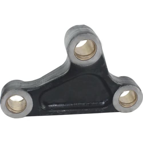
The Bell crank lever consists of two arms at right angles. Such types of levers are used in railway signaling, governors of Hartnell type, the drive for the air pump of condensers, etc. Let us design a simple Bell Crank Lever for one of these applications.
In this article, we will discuss how we can design a Bell Crank Lever for Hartnell Governor.
In a bell crank lever, the two arms of the lever are at right angles. Such types of levers are used in railway signaling, governors of Hartnell type, the drive for the air pump of condensers, etc. The bell crank lever is designed in a similar way as discussed in previous articles. The arms of the bell crank lever may be assumed of rectangular, elliptical, or I-section.
Let us discuss the complete design procedure for the bell crank lever with the following example.
A right-angled bell crank lever with a horizontal arm of 500 mm long and a load of 4.5 kN acts vertically downward through a pin in the forked end of this arm. At the end of the 150 mm long arm which is perpendicular to the 500 mm long arm, a force P act at right angles to the axis of the 150 mm arm through a pin into a forked end. The lever consists of forged steel material and a pin at the fulcrum.
Let us take the allowable stress in tension as 75 MPa, allowable stress in shear as 60 MPa, and allowable bearing pressure = 10 N/mm 2 for both the pins and lever.
Following is the bell crank lever schematic diagram with design parameters.
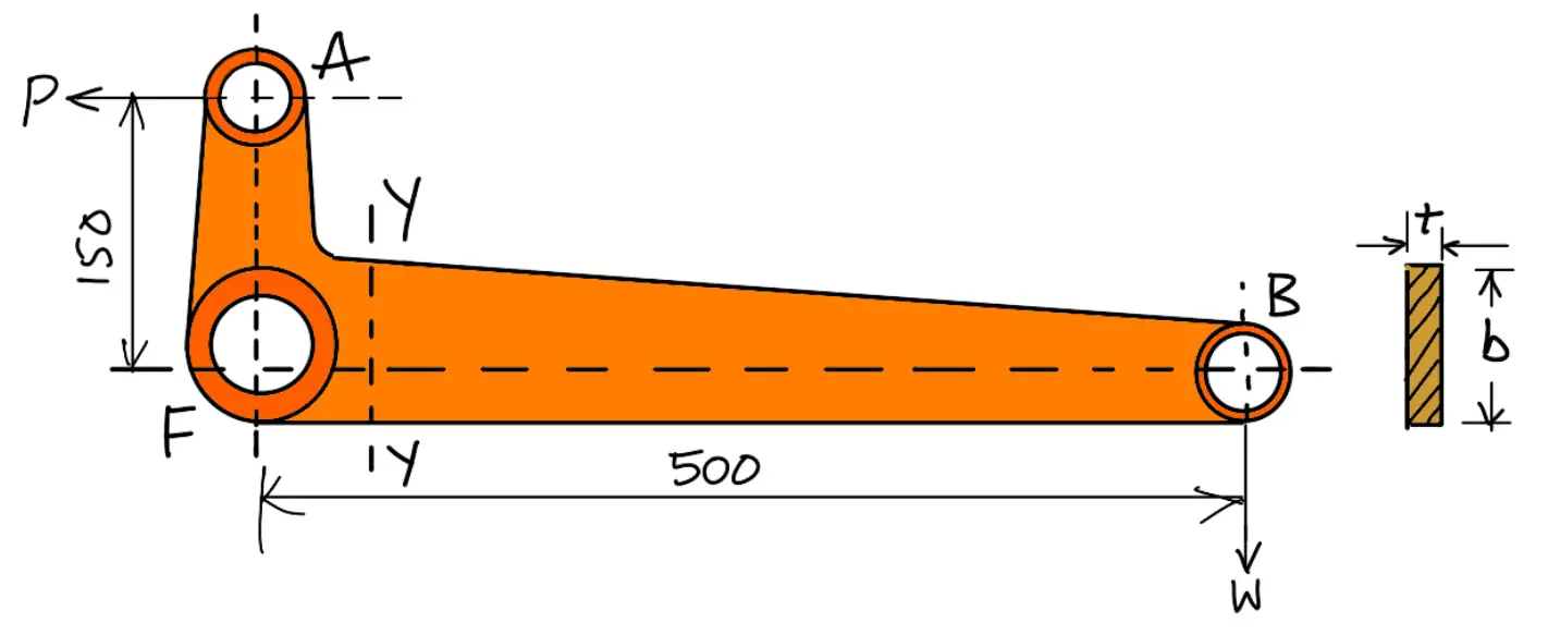
Known design parameters of the Bell Crank Lever are
FB = 500mm
W = 4.5kN = 4500N
FA = 150mm
σt = 75MPa =75N/mm 2
τ = 60MPa = 60N/mm 2
pb = 10 N/mm 2
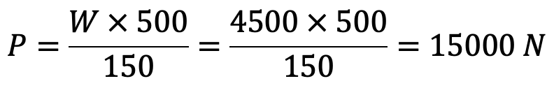
First of all, let us find the effort (P) required to raise the load (W).
Taking moments about the fulcrum F, we have
And reaction at the fulcrum pin at F,

Let,
d = Diameter of the fulcrum pin,
l = Length of the fulcrum pin l = 1.25d
Considering the fulcrum pin in the bearing. We know that load on the fulcrum pin (RF),
15660 = d × l × pb
15660 = d × 1.25d × 10
15660 = 12.5d 2
d 2 = 15660/12.5
d 2 = 1253
d = 35.4
Let us say the diameter of the fulcrum pin is 36mm.
The length of the fulcrum pin l = 1.25d = 1.25 × 36 =45mm.
Let us now check for the shear stress induced in the fulcrum pin. Since the pin is in double shear, therefore, a load on the fulcrum pin (RF)
15660 = 2 × π/4 × d 2 × τ
15660 = 2 × π/4 × (36) 2 × τ
15660 = 2036 τ
τ = 15 660/2036
τ = 7.7 N/mm 2
τ = 7.7 MPa
Since the shear stress induced in the fulcrum pin is 7.7 MPa, which is less than the given value of 60 MPa, therefore design for the fulcrum pin is safe.
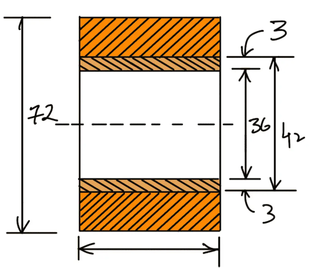
A brass bush of 3 mm thickness is pressed into the boss of the fulcrum as a bearing so that the renewal becomes simple when wear occurs.
∴ Diameter of hole in the lever = d + 2 × 3 = 36 + 6 = 42mm
Diameter of boss at fulcrum = 2d = 2 × 36 = 72mm
Now let us check the bending stress induced in the lever arm at the fulcrum. The section of the fulcrum is shown in the following figure
Bending moment at the fulcrum M = W × FB = 4500 × 500 = 2250 × 10 3 N-mm
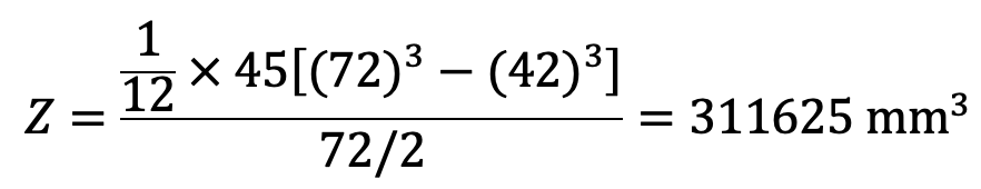
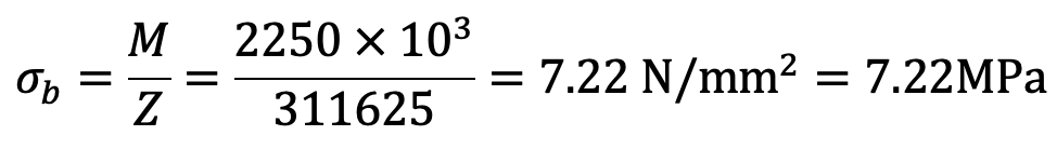
Since the bending stress induced in the lever arm at the fulcrum is less than the given value of 85 MPa, therefore it is safe.
Since the effort at A (which is 15 000 N), is not very much different from the reaction at fulcrum (which is 15 660 N), therefore the same dimensions for the pin and boss may be used for the fulcrum pin to reduce spares.
Diameter of pinat A = 36mm
Length of the pin at A = 45mm
Diameter of the boss at A = 72 mm
Considering the bearing of the pin at B. We know that load on the pin at B (W),
Let us say the Diameter of the pin at B as 20mm.
The length of the pin at B is l1= 1.25 d1 = 1.25 × 20 = 25mm.
Let us now check for the shear stress induced in the pin at B. Since the pin is in double shear, therefore load on the pin at B (W),
4500 = 2 × π/4 × d 2 × τ
4500 = 2 × π/4 × (20) 2 × τ
4500 = 628.4 τ
τ = 4500/628.4
τ = 7.16 N/mm 2
τ = 7.16 MPa
Since the shear stress induced in the pin at B is 7.16 MPa, which is within permissible limits, therefore the design is safe.
Since the end B is a forked end, therefore the thickness of each eye, t1 = l1 / 2 = 25/2 = 12.5mm.
In order to reduce wear, chilled phosphor bronze bushes of 3 mm thickness are provided in the eyes.
∴ Inner diameter of each eye = d1 + 2 × 3 = 20 + 6 = 26 mm
∴ Outer diameter of eye D = 2d1 = 2 × 20 = 40mm
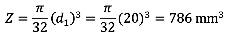
Let us now check the induced bending stress in the pin. The pin is neither simply supported nor rigidly fixed at its ends. Therefore the common practice is to assume the load distribution as shown in the following figure. The maximum bending moment will occur at Y-Y.
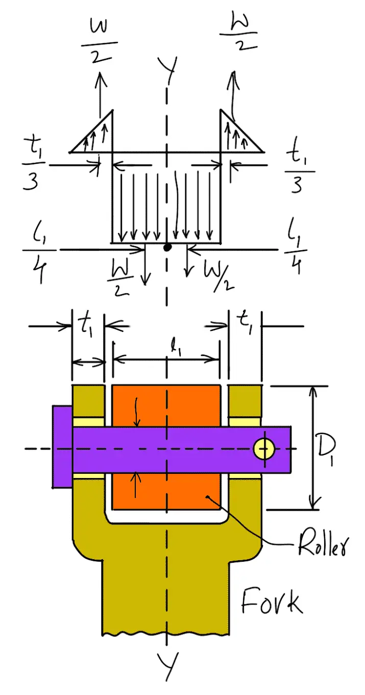
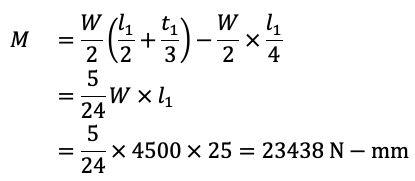
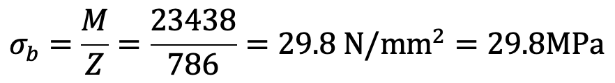
This induced bending stress is within safe limits.
It is assumed that the lever extends up to the center of the fulcrum from the point of application of the load. This assumption is commonly made and results in a slightly stronger section. Considering the weakest section of failure at Y-Y.
Let
t = Thickness of the lever at Y-Y
b = Width or depth of the lever at Y-Y.
Taking the distance from the center of the fulcrum to Y-Y as 50 mm, therefore maximum bending moment at Y-Y = 4500 (500 – 50) = 2025 × 10 3 N-mm
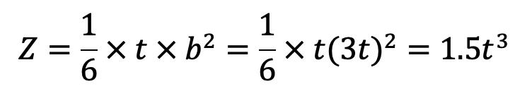
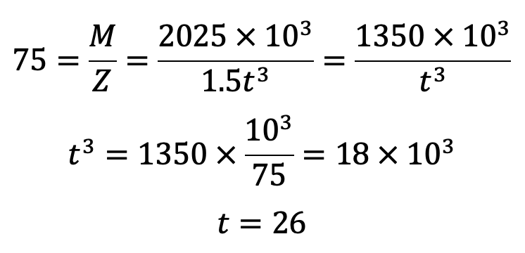
The thickness of the lever at Y-Y is t = 26mm.
The width or depth of the lever at Y-Y is b = 3t = 3 × 26 = 78mm.
Now we have all the design parameters for Bell Crank Lever for Hartnell Governor. Let us know what you think about this article in the comment section below.
Mechanical Engineer, Expertise in Engineering design, CAD/CAM, and Design Automation. More